Español
 عربى
 Deutsch
 русский
 Français

A maintenance technician calls it the weeping joint: a 3/8-inch connection on a 100 psi shop-air header that never quite seals, no matter how much tape goes on the thread. Nine times out of ten, two things are behind it. Either the male thread is NPT while the female port is BSPP — two standards that look similar on the bench but do not share a thread angle — or the fitting body was machined from a thin-wall, soft brass that ovalised the moment a wrench went on it.
The conclusion first: brass air fittings are specified, not shopped. Thread form, alloy and temper, and the sealing method decide whether a joint holds at line pressure; unit price only matters once those three are locked down. A fitting that costs two cents more and holds for ten years is cheaper than one that costs two cents less and drips into a ceiling panel for a decade.
What follows is a working guide for buyers, maintenance engineers, and product managers who source brass fittings for compressed air: how to identify thread standards before the first joint is made, which alloys survive wet air and vibration, how the main fitting families behave in service, what belongs on a purchase order, and how to test a joint before the system is pressurised for production.
Thread Form Comes First: NPT, BSPP, BSPT and Metric
NPT (ASME B1.20.1) is a 60-degree thread with a 1:16 taper. BSPT, also written R or Rc under ISO 7-1, is a 55-degree thread with the same 1:16 taper. BSPP, written G under ISO 228-1, is also 55 degrees but parallel — it seals on a bonded washer or an O-ring against a spot face, not on the thread itself. That difference in included angle looks trivial on a drawing and is practically invisible in a parts bin.
Pitch makes the trap worse, because it changes with size. At 1/8 inch, NPT runs 27 threads per inch and BSP runs 28. At 1/4 inch, NPT is 18 TPI against 19 for BSP. At 1/2 inch both standards settle on 14 TPI, so the pitches finally agree — but the 60-degree versus 55-degree flanks still mean the threads only touch on their edges. The joint starts easily, feels tight, and then weeps as soon as pressure arrives. The outside diameters differ slightly too, roughly 21.3 mm for a 1/2-inch NPT against 20.96 mm for BSP.
A caliper and a thread pitch gauge settle the question in under a minute. Measure the outside diameter at the thread end, then count threads across a known length and divide by that length in inches. Where a customer sends a sample with an uncertain thread, gauge it rather than guessing, and keep a set of go/no-go thread gauges for NPT, BSPT and BSPP at the sizes you sell most often. The cost of three gauges is less than one returned pallet.
| Standard | Included angle | Taper | Typical sizes | How it seals | Common where |
|---|---|---|---|---|---|
| NPT (ASME B1.20.1) | 60° | 1:16 | 1/8 to 2 in | Thread interference plus tape or paste | North America, many imported compressors and tools |
| BSPT / R / Rc (ISO 7-1) | 55° | 1:16 | 1/8 to 2 in | Thread interference plus sealant | Europe, Middle East, Asia, some Japanese equipment |
| BSPP / G (ISO 228-1) | 55° | Parallel | 1/8 to 2 in | Bonded washer, O-ring or metal seat | European ports, regulators, filter housings |
| NPS | 60° | Parallel | 1/8 to 1 in | Washer or gasket | Air tools, some spray equipment |
| Metric (M5×0.8, M10×1) | 60° | Parallel | M5, M10, M12 | O-ring or gasket | Mini cylinders, blow guns, compact valves |
| SAE 45° flare | Not applicable | Not applicable | 1/4 to 3/4 in tube | Flare cone formed on the tube | Automotive and low-pressure tube runs |
| JIC 37° flare | Not applicable | Not applicable | 1/4 to 1 in tube | 37° flare cone, metal-to-metal | Higher-pressure air and hydraulic tube |
Two rules follow from this. Never bridge standards inside a single joint to "make it work" — every adapter adds two threaded joints and two leak paths where there was one. And when a line is being designed rather than repaired, pick the standard of the equipment at the end of the run and stay with it, because a mixed header becomes unmaintainable once the original fitter has left the site.
Alloy and Temper: Where Cheap Brass Fittings Fail
Most brass air fittings on the market are machined from free-cutting brass, roughly C36000 or CuZn39Pb3: about 61.5 percent copper, 35.5 percent zinc, and 3 percent lead added to break chips so the part can be turned at high spindle speeds. It machines beautifully and carries modest strength — in the region of 340 MPa tensile in the half-hard condition. Forged bodies, which are what you want on anything above 1/2 inch or anything exposed to vibration, are usually made from forging brass such as C37700, at roughly 59 percent copper and 2 percent lead.
The zinc is the part that decides service life. In wet compressed air, condensate carries chlorides, carbon dioxide and dissolved solids onto the brass, and the zinc can leach out of the alloy, leaving a copper-rich, spongy surface. This is dezincification, and in the trade it shows up as red rot: the fitting turns pink, wall thickness falls away, and one day a joint that passed every test splits under a load it used to carry. Dezincification-resistant grades such as CW602N under EN 12165, or the inhibited silicon brasses, slow the process with small additions of arsenic, antimony or boron. If the fitting sits at the bottom of a wet header, in a drip leg, or on an outdoor line, DZR brass or bronze is worth the price difference.
Ammonia is the second hazard, and it is less widely understood. Brass that has not been stress-relieved can suffer stress corrosion cracking in an ammonia-bearing atmosphere, and the crack arrives weeks or months after installation with no visible warning. Food plants with ammonia refrigeration, certain agricultural and fertiliser environments, and some compressor oils that break down into nitrogen compounds all create the conditions. Where ammonia is present, specify stress-relieved fittings and consider bronze or stainless steel instead of leaded brass.
Temper and wall thickness matter as much as the alloy name. A fitting that deforms at the hex when it is tightened to 25 N·m has already lost its seal, and no sealant will recover it. Ask for half-hard temper and a stated minimum wall at the hex; a 5.5 mm wall on a 1/2-inch nipple behaves very differently from a 4 mm one when the same wrench is applied.
Plating is the last material decision. Electrolytic or electroless nickel at 3 to 8 micrometres gives a brighter finish, better resistance to condensate, and less thread galling on repeated assembly. It is a cosmetic and mild-corrosion measure, not a substitute for DZR brass in a wet header. If your specification calls for salt-spray performance, state the hours — 24, 48 or 96 to ASTM B117 — and state whether white corrosion or base-metal attack counts as failure, because suppliers will otherwise test to whichever standard flatters the part.
Lead content deserves its own line. Compressed air used for breathing, food contact or pharmaceutical production pulls the same restrictions as potable water, and many European and North American buyers now ask for under 0.25 percent lead or a full lead-free declaration even on air-only parts. EU RoHS carries an exemption for leaded copper alloys, but that exemption is reviewed on a fixed cycle, so a product designed around leaded brass today may need a redesign later. The wider material logic applied to water and air piping is set out in our guide to brass pipe fittings and their selection, and it applies almost unchanged to compressed air.
The Main Families of Brass Air Fittings
Air lines draw on the same brass catalogue as water lines, but not every part in that catalogue belongs on a compressed air header. These are the families that do, and the limits that come with each.
Threaded pipe fittings
Hex nipples, close nipples, couplings, reducing bushings, hex plugs, caps, elbows, street elbows, tees, crosses, bulkhead unions, extensions and locknuts form the skeleton of any header. They are simple parts with unglamorous failure modes: threads cut short so only four or five turns engage, walls thin enough that the hex distorts, or a reducing bushing tightened until the female port splits. Thread engagement should reach roughly five full turns on a 1/2-inch joint before sealant is counted, and the fitting should sit flush, not proud, against the port face.
Compression fittings
Two quite different products share the name. Industrial compression fittings use a brass olive or ferrule compressed onto copper, aluminium or nylon tube by a nut; with copper tube they hold working pressures comfortably above normal shop-air levels, which is why they dominate small machine and instrument lines. Automotive compression, used on air-brake lines, follows SAE dimensions and specific tube specifications. In both families, tube quality decides the outcome: a burr on the tube end or an out-of-round tube cuts the ferrule seat, and no amount of re-tightening recovers a scored cone. Cut square, deburr, insert fully, tighten by hand and then the specified fraction of a turn.
 GH-6019 Brass Compression Equal CouplingA forged brass equal coupling for joining same-diameter pipe without soldering or threading, suited to plumbing, heating and gas lines.View Product →
Push-to-connect fittings
Brass push-in fittings with a collet and an O-ring are the fastest thing to install on a machine retrofit, and they are increasingly the default in packaging and assembly cells. They have limits worth stating plainly. The O-ring is usually NBR, which is happy with mineral-oil carryover to about 80 °C and unhappy with phosphate-ester fluids, so specify FKM where temperature or chemistry demands it. Push fittings also want clean, dry air, because abrasive grit under the collet eventually scores the tube, and they are the wrong choice for a connection that will be broken and remade weekly at pressure. Tube must be cut square and pushed to the marked depth; a tube that stops 2 mm short looks assembled and leaks slowly.
Flare, barb and swivel fittings
SAE 45-degree flare suits copper and brass tube, JIC 37-degree suits higher-pressure steel tube, and hose barbs handle flexible drop lines to tools. Barbed brass fittings are usually the weakest pressure link in a drop line, and their rating should be quoted as a system — fitting plus hose plus clamp — rather than as a fitting alone. Swivel fittings solve alignment problems on tool drops but add an elastomer seal that ages, so keep a small stock of replacements.
Valves, filters and drains that live on air headers
Ball valves for isolation, Y-strainers ahead of regulators and tools, safety and relief valves on receivers, drain cocks at low points, and quick couplers at drop points. These are the parts that get operated, so they are also the parts that fail first. A ball valve that is only ever turned twice a year will seize; specify a valve with a documented pressure rating and a stem that can be exercised during maintenance rounds.
What the Air Itself Does to the Specification
Compressed air is not a benign fluid. It carries heat from compression, water from condensation, oil from the compressor, and dirt from the pipe. Each of those changes what a brass fitting has to survive, and each one shifts the answer away from the cheapest part in the catalogue.
Pressure sets the mechanical requirement. A typical workshop header runs 90 to 150 psi, or 6 to 10 bar; some production systems sit at 175 to 250 psi. Brass fittings rated at 150 psi are common in light-duty ranges, but that figure usually assumes ambient temperature and a static load. Add vibration from a piston compressor and thermal cycling across a shift, and the effective margin shrinks quickly.
Temperature is where brass fittings quietly lose their rating. A compressor discharge can reach 120 to 200 °C before the aftercooler, and no brass fitting should be bolted directly to a discharge port — use a flexible steel or PTFE-lined hose for the first metre and let the air cool before it meets brass and elastomer. As a working rule, at 100 °C a fitting rated for 10 bar at 20 °C is operating with roughly half its room-temperature strength, and its seals are ageing several times faster than the datasheet assumes.
| Air condition | Typical value | Fitting approach | Watch-out |
|---|---|---|---|
| General shop air | 6 to 10 bar, 20 to 40 °C | Machined or forged brass, NPT or BSPP, tape or anaerobic paste | Undersized wall at the hex |
| Piston compressor discharge | 120 to 200 °C before cooling | Flexible metal hose first; no brass within the first metre | Elastomer seals degrade fast |
| Wet header and drip legs | Near saturation at low points | DZR brass or bronze with a drain cock | Dezincification and red rot |
| Mobile and air-brake lines | 8 to 10 bar plus vibration | SAE or DOT-rated brass only | Non-rated fittings break compliance |
| Vacuum pick-and-place | −0.8 bar | Push-to-connect with tube support sleeve | Collet creep and slow leak |
| Food, breathing or medical air | Oil-free, dry, monitored | Lead-restricted brass with material certificates | Lead content and oil carryover |
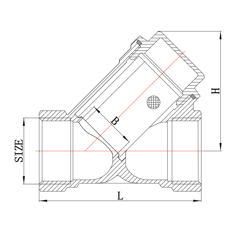 GH-5001 Brass Y-Type Pipeline StrainerA forged brass Y-strainer with an accessible screen for trapping debris before valves and regulators; rated 1.6 MPa for water and non-corrosive liquids.View Product →
Condensate is the slow killer. Water collects at low points, in dead legs and in drop pipes below the header, and that is exactly where fittings sit wettest for longest. Slope headers back to a drain, fit a drip leg with a drain cock at each low point, and specify a strainer ahead of every regulator so that pipe scale does not reach a seat or a solenoid. A Y-strainer costs a fraction of the valve it protects and takes five minutes to clean.
Oil carryover attacks seals rather than metal. Mineral oil swells NBR modestly and is usually tolerated; synthetic oils, especially phosphate esters and some polyglycols, attack it badly. If the compressor is oil-flooded and the downstream process is oil-sensitive, the answer is filtration rather than a more exotic fitting, but the seal material still has to match the lubricant.
Sealing Threads: Tape, Paste, and Torque Discipline
Most leaks blamed on fittings are sealant problems. PTFE tape works, but it works in a specific way: two to three wraps in the direction of the thread helix, starting one or two threads back from the pipe end, with the tape pulled slightly so it beds into the roots. Tape that overhangs the end of the fitting breaks off during assembly and travels downstream into regulators, solenoid valves and instruments, which is why so many "valve failures" begin with a fitting that was taped carelessly.
Anaerobic thread sealant is generally the better choice on taper threads. It lubricates during assembly, cures in the absence of air into a solid that fills the spiral gap, and does not shred. It also does not migrate. Paste has the advantage of being visible during inspection and easy to identify on a disassembled joint.
Parallel threads are a separate discipline. BSPP and metric ports with a sealing washer or O-ring do not need tape at all; wrapping tape around a parallel thread achieves nothing except a false sense of security and a washer that no longer seats squarely. The sealing face must be clean and undamaged, and the washer must be the right hardness and thickness for the port.
Torque guidance for brass taper threads sits in a narrow band. Typical starting ranges are about 7 to 10 N·m at 1/8 inch, 12 to 18 N·m at 1/4 inch, 20 to 28 N·m at 3/8 inch, and 25 to 35 N·m at 1/2 inch. Treat those as starting points and confirm against the manufacturer's data, because a forged body and a thin-wall machined body do not take the same load. Tighten to seal, not to destroy: three turns past hand-tight is normally sufficient on a taper thread, and anything beyond that is deforming the female port rather than improving the seal.
Two components should never see sealant at all: flare cones and compression ferrule seats. Both seal metal-to-metal by deformation, and a film of tape or paste in that interface is a leak path, not a cure.
Testing a Joint Before the Line Goes Live
Testing is cheap; discovering a leak above a suspended ceiling is not. A short, repeatable sequence catches almost everything that assembly gets wrong.
- Assembly check: confirm thread standard, engagement depth, correct washer on parallel ports, and no visible tape fragments at any port face.
- Low-pressure bubble test: pressurise to 1 to 2 bar and brush a 1 to 2 percent soap solution on every joint. Bubbles at this stage are almost always assembly errors, not material defects.
- Working-pressure decay test: cap all outlets, pressurise to the design working pressure, isolate the supply and log the gauge for 10 to 15 minutes. Allow for temperature drift, because a rising ambient will mask or mimic a leak.
- Elevated test: repeat at 1.25 to 1.5 times working pressure for a short, controlled period where the system design permits it. This is where porosity and thin walls reveal themselves.
- Instrument check: for sensitive systems, use an ultrasonic leak detector, which finds leaks in the range of grams per year that soap bubbles will never show.
- Retest after 24 hours: vibration and thermal cycling settle joints, and a fitting that passed cold may weep after a shift of running.
Pneumatic testing stores energy, so treat it with respect: use guards, remote gauges, and never stand in line with a plug or a cap that could become a projectile. Where a system is large, a hydrostatic proof test on the components at the factory plus a pneumatic leak test on site is the safer combination.
Failure Modes You Will Actually See
Field returns cluster into a small number of patterns, and each pattern points at a specific decision made long before the failure.
- Weeping taper joint: mismatched thread standard, insufficient engagement, or sealant applied to the wrong part of the thread.
- Split at the hex: over-torque on a thin-wall body, or a body machined from soft temper that deformed before the thread seated.
- Red rot at a low point: dezincification in a wet drip leg where a standard leaded brass was used instead of a DZR grade.
- Unexplained cracking months after installation: ammonia stress corrosion, usually in a food or refrigeration environment, and usually on a part that was never stress-relieved.
- Fatigue fracture next to a compressor: an unsupported fitting taking vibration directly, with no flexible section to absorb it.
- White or green crust where brass meets a steel bracket: galvanic corrosion in a damp outdoor location, solved by an insulating washer or a different bracket material.
- Swollen or hardened seal: elastomer incompatible with the compressor lubricant, not a fitting defect at all.
- Blocked regulator or solenoid: tape fragments, pipe scale or thread debris that travelled downstream from a badly made joint.
Reading a failure correctly saves money. If three joints on one header split at the hex, the problem is not the alloy — it is the torque spec, or the absence of one. If the same low point rots twice, the problem is drainage, not the fitting.
A Purchase Specification You Can Send Out Today
Most disputes after a shipment trace back to a purchase order that named a product but not a requirement. A one-page specification closes that gap, and it takes less time to write than a single round of email argument.
| Specification item | Example value | Why it matters |
|---|---|---|
| Material grade | C36000 or C37700, with heat certificate | Sets strength, machinability and corrosion behaviour |
| Temper and wall | Half-hard, minimum 5.0 mm wall at the hex | Prevents deformation under normal torque |
| Thread | ASME B1.20.1 NPT, checked with go/no-go gauges | Stops cross-standard mix-ups at the port |
| Dimensions | Per approved drawing, key dimensions with tolerances | Interchangeability with existing equipment |
| Plating | Nickel 5 to 8 µm, ISO 1456, 48 h salt spray | Condensate resistance and consistent appearance |
| Pressure rating | 16 bar at 20 °C, proof tested at 1.5 times | Usable safety margin, not a catalogue claim |
| Leak test | 100 percent air test at 10 bar for 30 s, no bubble | Catches porosity and thread defects before packing |
| Compliance | RoHS, REACH SVHC declaration, lead under 0.25 percent | Acceptance in European and North American markets |
| Packaging | Inner carton, pallet, desiccant, label per part number | Freight damage and mixed-carton errors |
| Quality level | AQL 1.0 major / 2.5 minor | Agreed sampling before the container leaves |
Two lines are worth adding beyond the table. First, a statement of what happens with a non-conforming lot — replacement, credit or rework — agreed before the first order rather than after the third. Second, a requirement that the supplier name the test method for every claim. "Corrosion resistant" is not a specification; "48 hours neutral salt spray to ASTM B117 with no base-metal attack" is.
Matching Fittings to Valves, Filters and Drains
An air line is a system, and fittings only perform as well as the components around them. Isolation valves belong at every branch so a single tool can be serviced without dumping the header; strainers belong ahead of regulators and solenoid valves; drain cocks belong at every low point and at the receiver; and a relief valve belongs wherever a regulator could fail closed against a dead-ended volume.
Where the whole set is sourced together, the fitting and valve threads have to agree by design rather than by luck. A factory that machines brass bodies, assembles them, and pressure tests above the rated working pressure can hold that consistency across a mixed order, which is why many buyers pair fittings with the valves that sit next to them. A brass ball valve with a female-by-female thread, exercised at commissioning and annually after that, is the simplest insurance against a Saturday callout.
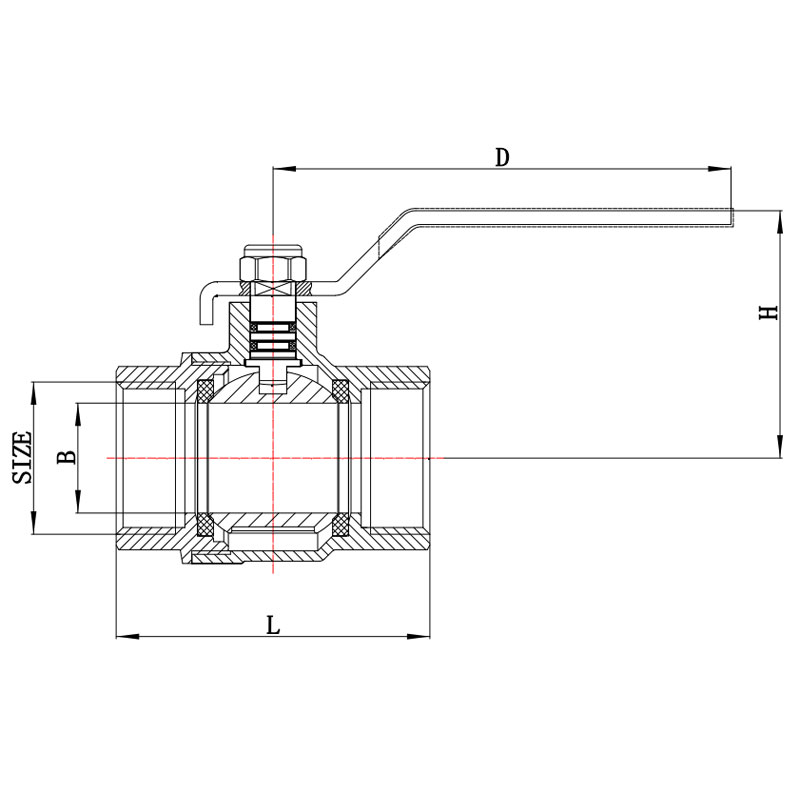 GH-1001 Brass Female-Thread Ball ValveA forged brass full-port ball valve with female threads and lever handle, offering quick isolation for water, air, gas and non-corrosive systems.View Product →
The overlap between the water-side and air-side catalogue is large. A manufacturer that already produces brass fittings, ball valves, strainers, drain valves and safety valves for plumbing and HVAC usually has the tooling, thread gauges and test benches needed for compressed air work as well — see the brass valve and fitting range for how those parts group together. The specification changes; the manufacturing discipline does not.
Sampling, First Article Approval and Order Discipline
Before a container ships, three documents are worth having. The first is an approved drawing, signed by both sides, that shows every dimension that matters with a tolerance. The second is a first article inspection report — dimensional results from a coordinate measuring machine or hand gauges, thread gauge results, plating thickness by X-ray fluorescence, and a leak test record. The third is a material certificate traceable to the heat number, not a generic alloy statement.
On the factory side, the questions that separate a reliable supplier from an optimistic one are practical. How many production and test stations are in the plant, and are they dedicated to brass or shared with other metals? Is every piece pressure tested, or sampled? What is the test pressure relative to the working pressure? Which process steps are in-house — rod cutting, forging or casting, precision machining, nickel plating, assembly, testing, packing — and which are subcontracted? A factory that performs cutting, forming, machining, plating, assembly and pressure testing under one roof controls its own lead time; one that subcontracts plating does not.
Order discipline matters as much as supplier selection. Mixed cartons save freight and create picking errors. Model numbers that differ by one character, such as a lockable and non-lockable version of the same valve, are the most common source of wrong-part shipments in this category, so ask for labels that carry both the model number and a short description. Agree on packaging for export: inner cartons strong enough to survive a pallet stack, desiccant in humid seasons, and a pallet pattern that will not crush the bottom layer.
Worked Example: A 3/4-Inch Air Header for a Small Workshop
A workshop with two compressors, six drop points and a spray booth needs a header that can be serviced without shutting the plant. Here is how the decisions fall out in practice.
- Set the standard. The compressors and tools are NPT, so the entire header is NPT, with BSPP adapters only at the imported filter housings and only at the point of use.
- Size the pipe for pressure drop, not for the compressor outlet. A 3/4-inch header fed by a 1/2-inch outlet is normal; sizing the header to the largest single tool rather than to total simultaneous demand is not.
- Specify material by location. Dry indoor runs use standard free-cutting or forging brass; the drip legs at each low point and the run to the outdoor washdown bay use DZR brass or bronze.
- Choose the seal per thread type. Anaerobic paste on all taper joints, bonded washers on the parallel filter ports, no tape anywhere near a flare or compression seat.
- Put a valve at every branch. Six ball valves, female by female, with a documented rating of 16 bar at ambient, isolate each drop so a hose repair does not stop the spray booth.
- Strain before regulating. A Y-strainer at the inlet to each regulator catches the scale that would otherwise reach a seat, and the screen is cleaned at the first service interval rather than at the first complaint.
- Test in stages. Each branch is bubble tested at 2 bar as it is assembled, the whole header is decay tested at working pressure for 15 minutes, and the system is re-checked after the first full shift of running.
None of those steps is exotic. The reason headers still leak is that one of them gets skipped — usually the thread standard check at the filter housing, or the re-test after a shift of thermal cycling.
Brass air fittings are a mature product, and the failures that reach maintenance teams are rarely mysterious. A joint that weeps is almost always a thread standard that was never confirmed, a wall that was too thin for the wrench that met it, or a sealant applied to the wrong surface. A fitting that fails after a year is usually a material decision: leaded brass in a wet drip leg, an unrestrained body next to a piston compressor, or a part that was never stress-relieved in an ammonia-bearing plant.
The practical route is to specify before you shop. Name the thread standard and the gauge that proves it. Name the alloy, temper and minimum wall. State the pressure rating and the test that verifies it, along with the plating thickness and the compliance declarations the destination market requires. Then test in stages — bubble at low pressure, decay at working pressure, re-check after a shift — and keep the records, because a documented joint is the only kind that can be defended later.
Get those three decisions right, and the rest of the air line becomes ordinary: standard parts, predictable lead times, and a maintenance schedule built around filters and drains rather than around leaks.